AC/DC to DC converter
Tuyen D. Le March 31, 2022 [Power-Electronics] #AC-DCIf you don't know what is K1 L1 L2 1 transformer directive means, you should check 1 for more details.
1. Forward converter
1.1. One-switch sigle-ended forward converter (isolated buck converter)
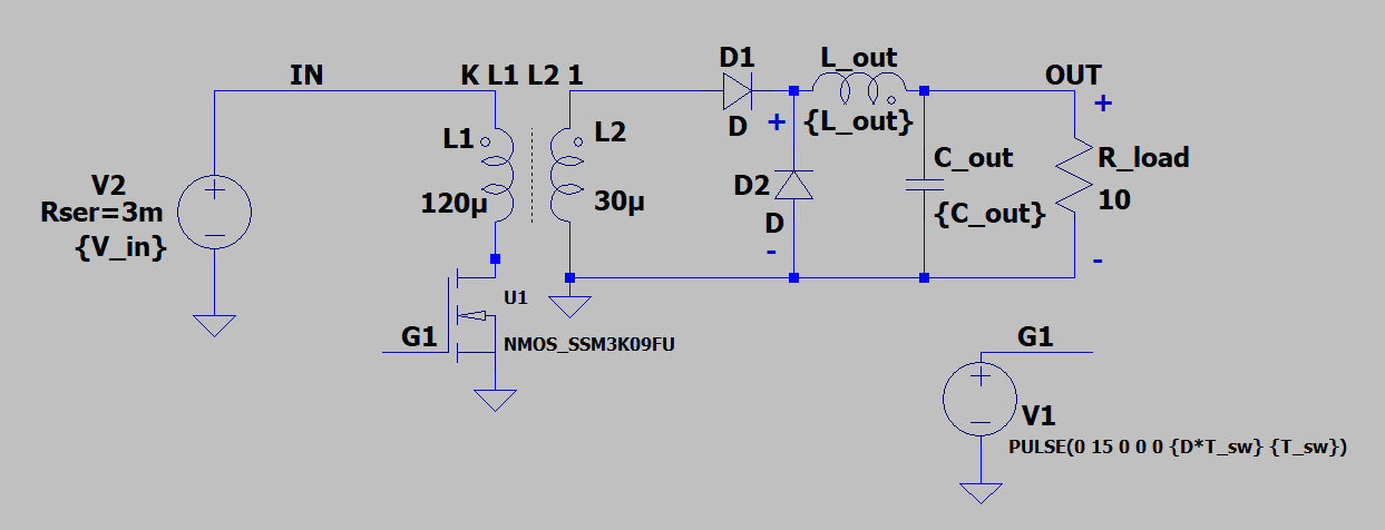
This is essentially a buck converter with transformer inserted.
We want to operate in Continuous Conduction Mode. $I_{Lout}$ never reach zero.
In DCM we may have peak detect phenomina, we $V_{out}^{'} = (3-4) \times V_{out}$
ESR is from $C_{OUT}$, and $\Delta I$ is effected by the design of $L_{out}$. Rule of thumb is $\Delta I$ = 10% to 40% of full load.
Refer 2 for more details.
1.2. Two-switch sigle-ended forward converter (isolated buck converter)
also called asymmetrical half bridge forward
2. Flyback converter
Transfer function 3 is
where $n$ is turn ration, and $D$ is duty cycle.
2.1. RCD Clamp
- See more at RCD Clamp
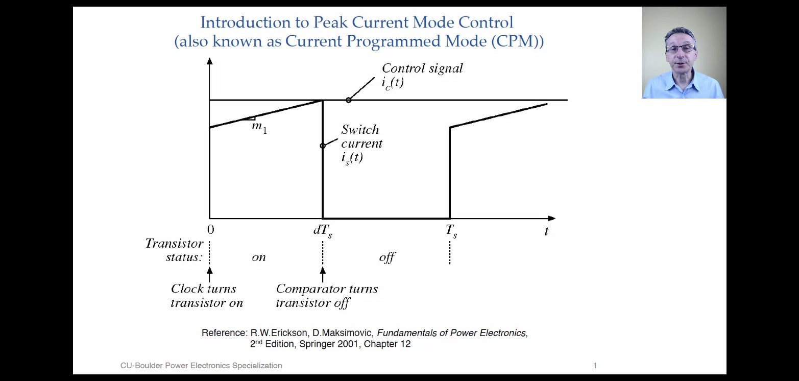
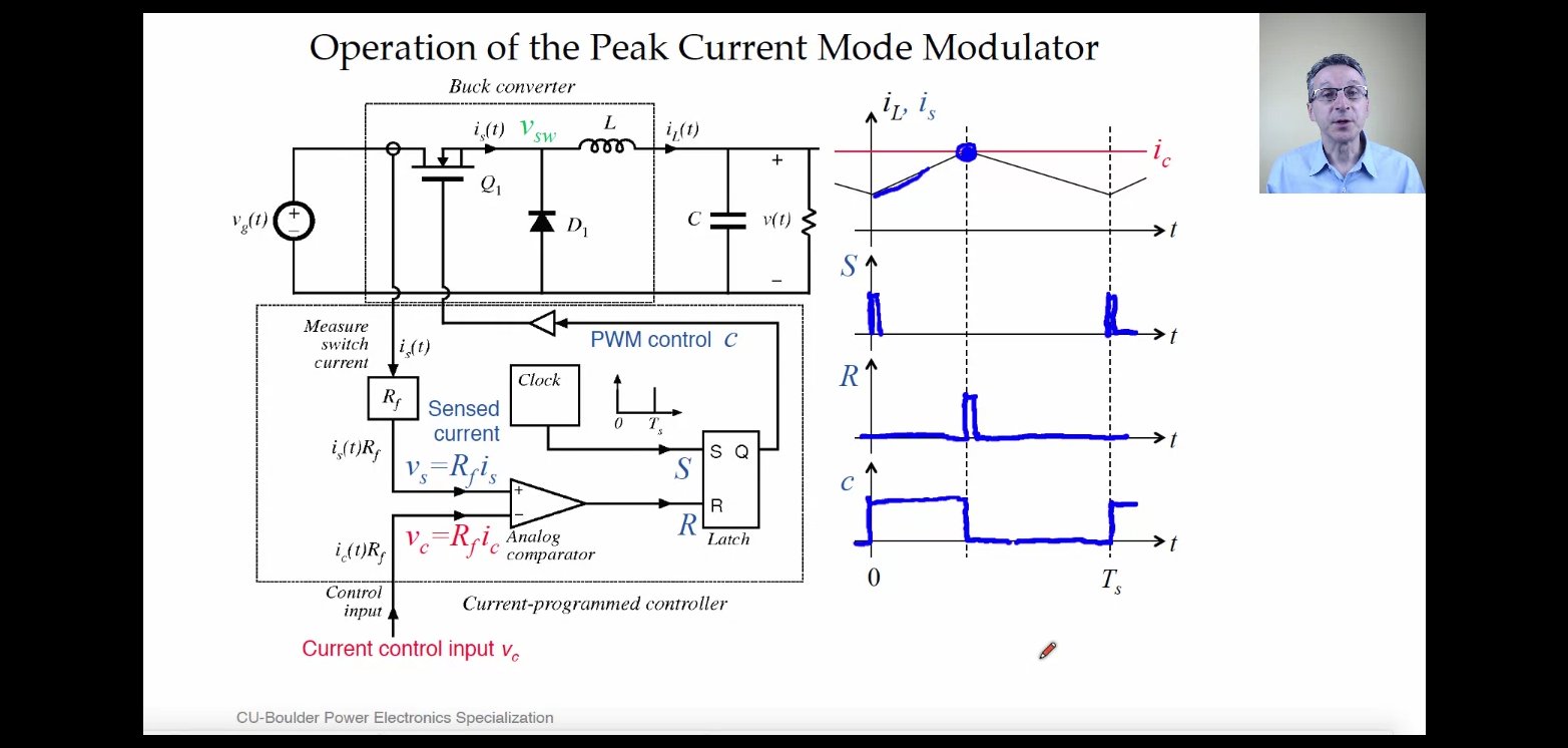
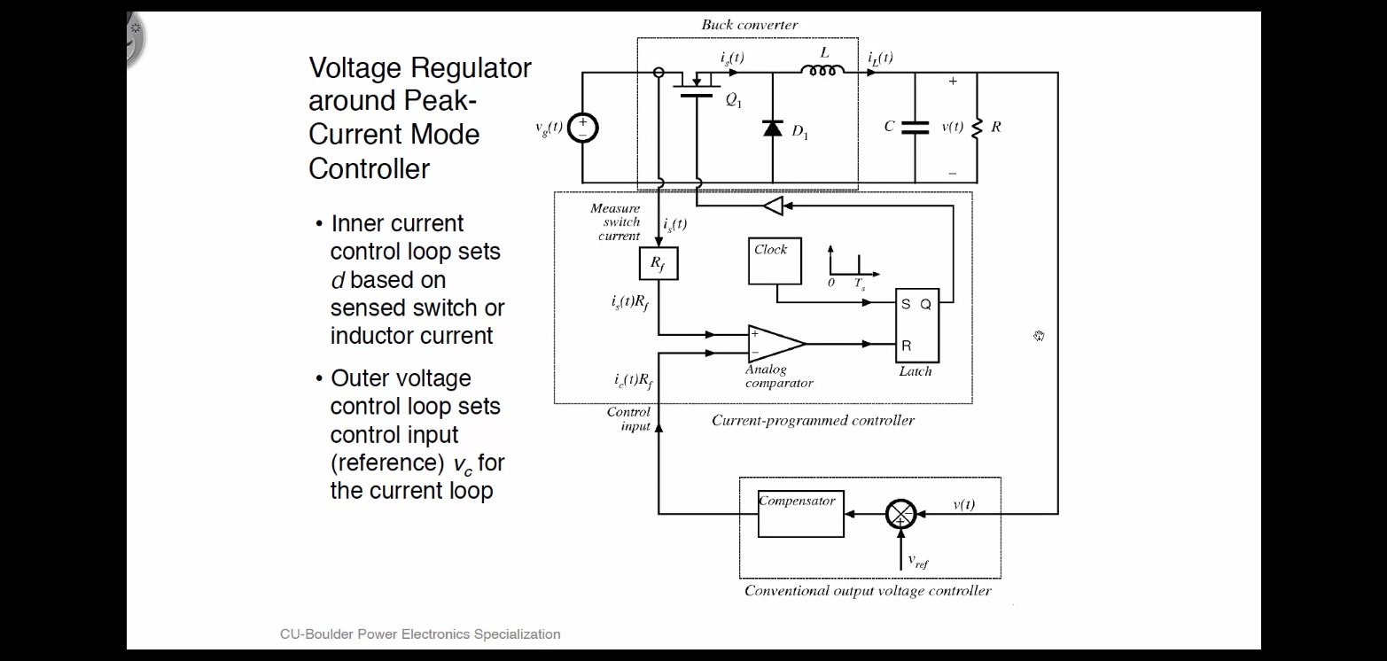
3. Peak current control mode (Current-Programmed Control)
UCC28C42 from TI using this control method.
Refer to chapter 18 of 4, and 5.
4. Slope compensation
Refer to 6 for more information.
 |
|---|
| D<50% turburlance is faded out |
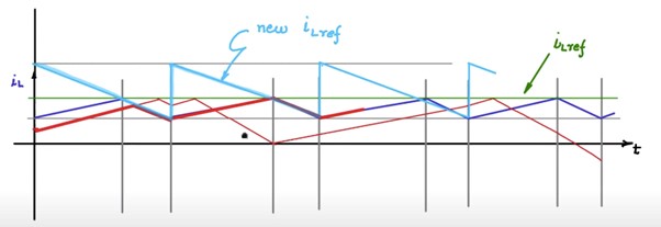
If Duty cycle $D>50%$, $I_L$ with turburlance is not stable.

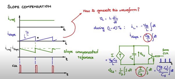
Using new $I_{Lref}$ to solve the problem.
How to generate the new $I_{Lref}$?
5. Practical consideration
5.1. How to use Impedance Analyzer
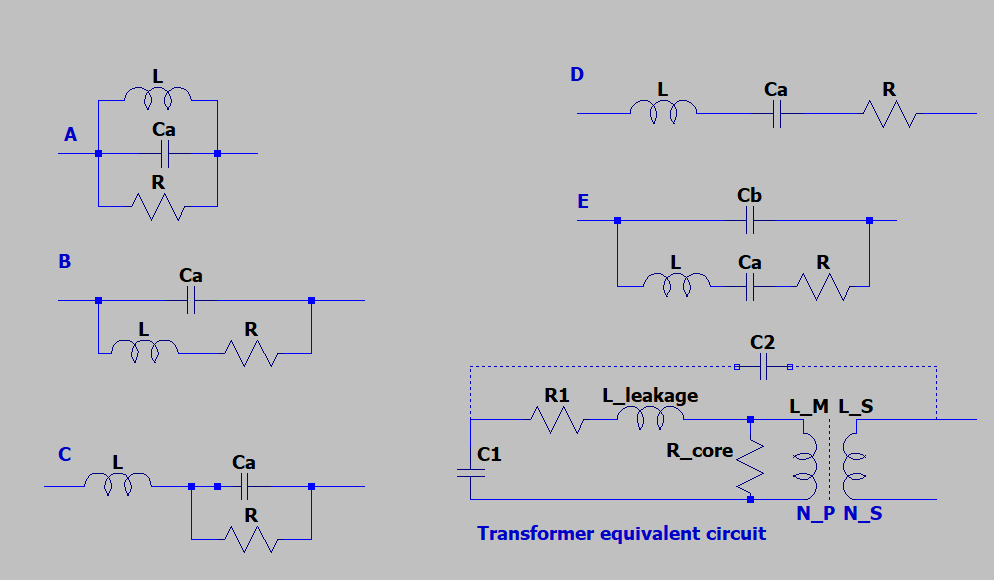
The table is adapted from 7.
| Equi. circuit | Type of DUTs |
|---|---|
| A | (1) Coils with high core loss; (2) To measure magnetizing inductance $L_M$, you need to open the secondary side. Only $L_M,C_1,R_{core}$ were left. |
| B | (1) coils in general; (2) resistors; (3) Measuring leakage inductance $L_{leakage}$, you need to short the secondary side. |
| C | High value resistors |
| D | Capacitors |
| E | Resonators (crystal, ceramic, ferrite) |
Pending
- https://archive.nptel.ac.in/course.html
- NOC:Fundamental of Power Electronics (Video)
- Week 12
- Intro for close loop control
- Close looping dc-dc converters
- Simulation of close loop control
- Current control for battery charger application
- Instability in current control and slope compensation
- Slope compensated current control
- Simulation of current control
- Single phase inverter with sinusoidal pwm
- Simulation of sinusoidal PWM
- Week 12
- NOC:Control and Tuning Methods in Switched Mode Power Converters
- Week 02
- Lecture 12 : Interactive MATLAB Simulation and Case Studies
- Week 02
6. References
David Perreault. 6.334 Power Electronics Ch. 7. Spring 2007. Massachusetts Institute of Technology: MIT OpenCourseWare, https://ocw.mit.edu. License: Creative Commons BY-NC-SA.
Operation manual Model 4191A network/spectrum Analyzer page 141/356 Online
Erickson, R. W. & Maksimovic, D. 2007. Fundamentals of power electronics, Springer Science & Business Media.
Current-Mode Control, Dr. Dragan Maksimovic - University of Colorado Boulder Online
Slope compensation for current control - NPTEL Online
AC Modeling of Power Stage in Flyback Converter - Texas Instruments Online