Control of grid connected inverter
Tuyen D. Le February 24, 2022 [Power-Electronics] #grid1. Fundamental terminologies
1.1. Power
The instantaneous electrical power P delivered to a component is given by
where
- $P(t)$ is the instantaneous power, measured in watts (joules per second)
- $V(t)$ is the potential difference (or voltage drop) across the component, measured in volts
- $I(t)$ is the current through it, measured in amperes
The average power is
1.2. What is postitive, negative and zero sequence?
These components are so-called symmetrical components 1.
⚠️ Note:⚠️ The author was used $\underline{z}$ to denote a vector. However, I am using $\vec{z}$ to do this because of my personal preference.
Symmetrical components allow unbalanced phase quantities such as currents and voltages to be replaced by three separate balanced symmetrical components
The transformation is defined as:
The invert transformation is:
Let take an example. Obtain the symmetrical components of a set of unbalanced voltage.
Run this Matlab script to get the result.
methods
function [v_out_theta, v_out_rho]
%% Symmetrical Components Theory
% va: Unbalanced phase A voltage
% vb: Unbalanced phase B voltage
% vc: Unbalanced phase C voltage
%
% v_out_theta_d: Output theta in degree/radian (polar form)
% v_out_rho: Output radius (polar form)
% ┌─ ─┐ ┌─ ─┐ ┌─ ─┐
% │V_pos│ = 1/3 │1 α α^2│ │V_a│
% │V_neg│ │1 α^2 α │ │V_b│
% │V_0 │ │1 1 1 │ │V_c│
% └─ ─┘ └─ ─┘ └─ ─┘
uint8 = 0
end
= 1;
= 2 * pi /3;
alpha = * exp ;
= 1 /3 * ;
= ;
= * ;
= cart2pol;
if
= 180* / pi;
end
end
end
end
%% symmetrical components
clc;
clear;
% Input
= 5 * exp;
= 7 * exp;
= 7 * exp ;
% result is in Degree unit
fprintf;
= lib.sym_components_theory ;
fprintf; disp;
fprintf; disp;
% Draw complex number
= .* exp ;
= ;
= ;
= ;
= ;
t.Padding = 'compact';
t.TileSpacing = 'compact';
% unbalanced voltage
= ;
= ;
= compass;
title
text
= ;
c_b.Color = 'g'; % V_b is green
text
= ;
c_c.Color = 'r'; % V_c is red
text
% positive voltage sequence
= ;
= ;
= compass;
title
= ;
c_pos_b.Color = 'g'; % V_b is green
= ;
c_pos_c.Color = 'r'; % V_c is red
%negative voltage sequency
= ;
= ;
= compass;
title
= ;
c_neg_b.Color = 'g'; % V_b is green
= ;
c_neg_c.Color = 'r'; % V_c is red
% Zero sequences
= ;
= compass;
title
%----------------------------------------------------
%% Unbalanced current
= 10;
= 10 * exp;
= 0;
= lib.sym_components_theory

We get $V_+, V_-, V_0$ magnitude and phase accordingly.
+ - order.
:
5.0156
1.9469
3.4718
:
-10.2643
92.4259
122.0788
or, it could be written in the time domain form.
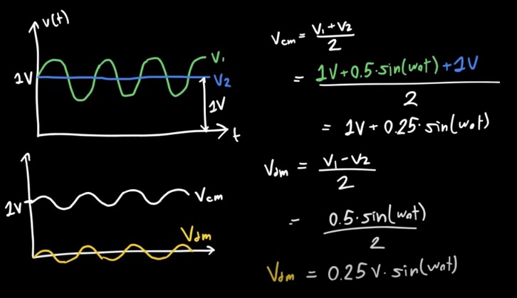
1.3. Differential and Common Mode Signals
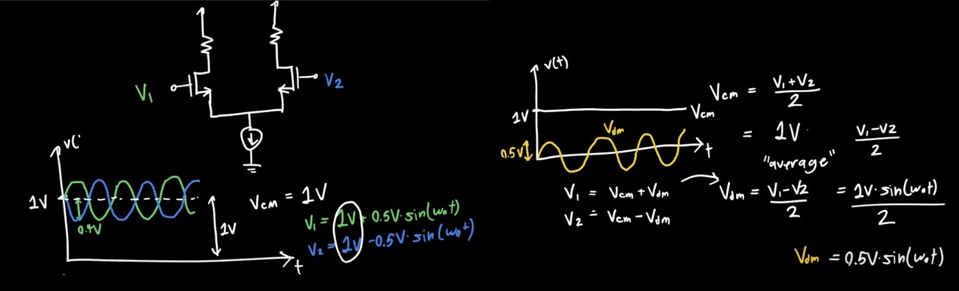
An other example.
1.4. References
- 1: James Kirtley Jr.. 6.061 Introduction to Electric Power Systems. Spring 2011. Massachusetts Institute of Technology: MIT OpenCourseWare, https://ocw.mit.edu License: Creative Commons BY-NC-SA.
- Calculate Powers in Non-sinusoidal Conditions According to IEEE 1459
- Differential and Common Mode Signals
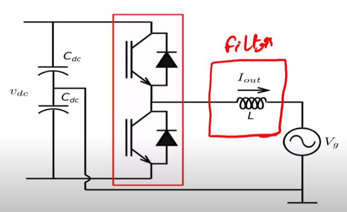
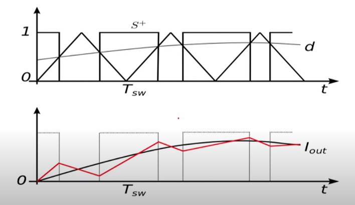
2. Filter design
2.1. L filter
2.2. References
- AC filters for grid connected inverters in Power electronic design.
- Three-phase grid converter control: video 1 Grid tied inverters
3. Phase-locked loop
References
- https://dsp.stackexchange.com/q/75492
- Three-phase grid converter control: video 3 Phase lock loops