The fundamental of DC-AC inverter
Tuyen D. Le January 13, 2022 [Power-Electronics] #DC-ACRefer 1 for more details.
Getting started
Switch utilization
$$ \frac{P_o}{P_T} = \frac{V_{o1,max} \times I_{o1,max}}{q \times V_T \times I_T} $$
Where
- $V_{o1,max}, I_{o1,max}$ are the maximum rated output voltage and current.
- $V_T, I_T$ are the peak voltage rating and peak current rating of a switching device.
- $q$ is the number of switches.
1. Full-brige inverters
TL;DR
- Unipolar by definition: having or oriented in respect to a single pole.
- Bipolar by definiton: having or involving the use of two poles or polarities.
Where:
- $M$ is mudulation index.
- $\omega$ is fundamental frequency.
- $f_{sw} = 1 / T_{sw}$ is switching frequency.
Refer to 2 for LTspice simulation instruction.
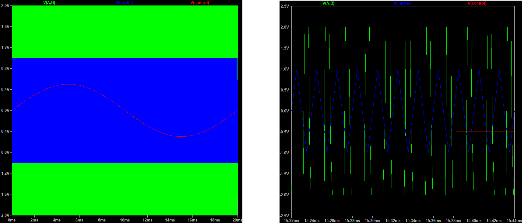
1.1. Biploar PWM
S1 and S4 turn on and turn off at the same time.
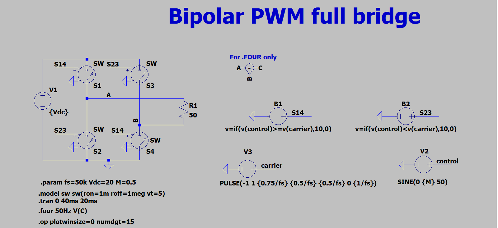
Simulation result:
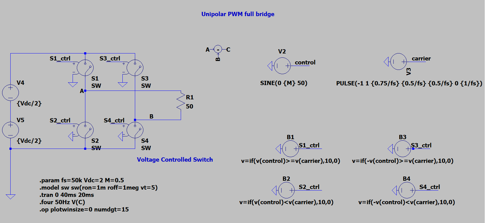
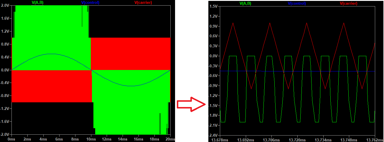
1.2. Unipolar PWM
The inverter output voltage switches between either between $0 \rightarrow +Vd$ during half cycle and $0 \rightarrow -Vd$ half cycle of the fundamental frequency thus this scheme is called unipolar modulation.
1.3. Hybrid PWM
Refer to 3
References
- 3: Lai, R.S. and Ngo, K.D., 1995. A PWM method for reduction of switching loss in a full-bridge inverter. IEEE Transactions on Power Electronics, 10(3), pp.326-332.
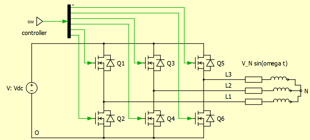
2. Vector space and three-phase inverter
3. Power losses and heating design of an DC-AC inverter
Power losses of an inverter is defined as
$$ P_{Loss} = P_{in} - P_{out} $$
We could measure the losses in two ways.
- Direct measure $P_{in}$ and $P_{out}$. The stability of this method is difficult to achieve. A small variant in input or output could lead to a large error.
- Indrect by using Calorimetric methos. Highest accuracy is achieved, but it is complicate to operate.
A alternative of measuring the losses is deriving the losses. The losses can be calculated by estimate of 4 types of power losses.
- Switching losses
- Conducting Losses
- Blocking losses (neglecgable)
- Driving losses (neglecable)
The rule of thumb for a good design is 50% of switching losses and 50% of conducting losses. Let take a closer look at the three-phase inverter.
$$ P_{conduction} = \frac{1}{2 \pi} \int_{0}^{2 \pi} v (\omega t) i (\omega t) dt $$
Power switch is only conducting for half of period.
$$ \text{Note: } V_{CE,0}, ; R_{CE}, ; R_{DS}, ;V_{F,0}, ; R_{F} \text{ are from the datasheets of Mosfet/IGBT/Diode.} $$
Using Kirchhoff's current law, we have,
$$ i_{IGBT} (\omega t) + i_{Diode} (\omega t) = \hat{i}_N ; sin(\omega t) $$
where:
In case of Sine-triangle PWM modulation, modulation function $m = M \cdot sin(\omega t + \phi)$ with $M$ is modulation index.
we have,
Replace equation (1) by equation (3) we get,
Finally, we get the important formular for conduction losses.
Since $R_{DS} \gg R_{CE}$, we could say that $P_C^{MOS}$ is not smaller than $P_C^{IBGT}$.
Switching losses
$$ \begin{align*} & P_{SW,IGBT} = \frac{1}{\pi} f_{SW} (E_{on} + E_{off}) \frac{V_{DC}}{V_{ref}} \frac{\hat{i_N}}{i_{ref}} \ & P_{SW,Diode} = \frac{1}{\pi} f_{SW} E_{rec} \frac{V_{DC}}{V_{ref}} \frac{\hat{i_N}}{i_{ref}} \ & \text{ where } E_{rec} = \frac{1}{2} V_{rr} \times Q_{rr} \end{align*} $$
4. References
David Perreault. 6.334 Power Electronics. Spring 2007. Massachusetts Institute of Technology: MIT OpenCourseWare, https://ocw.mit.edu. License: Creative Commons BY-NC-SA.
MOSFET Power Losses Calculation Using the DataSheet Parameters